Wednesday, March 17, 2010
Write Program - Second move
void breakdance()
{
revOn
leftOn
delay_ms (5000);
revOff
leftOff
delay_ms (1000);
fwdOn
rightOn
delay_ms (1000);
The “while (TRUE)” is a simple way to create a loop that never stops.
Write Program
Secondly, we write the program in the PIC C Compiler. Here, we use C programming type of coding.
#include <16F877A.h> //specify the MCU
#fuses HS,NOLVP,NOWDT //high speed, no low voltage programming, no watchdog timer
#use delay (clock=20000000) //set the clock to 20MHz
The first three lines of this program define the basic hardware environment. The chip being used is the PIC16F877A, running at 20MHz.
The “output_low” turns the LED on because the other end of the LED is +5V. This is done because the chip can tolerate more current when a pin is low than when it is high.
#define fwdOn output_high (pin_b1);
#define fwdOff output_low (pin_b1);
#define revOn output_high (pin_b2);
#define revOff output_low (pin_b2);
#define leftOn output_high (pin_b3);
#define leftOff output_low (pin_b3);
#define rightOn output_high (pin_b4);
#define rightOff output_low (pin_b4);
The #define is used to enhance readability the code that assigned at the pin that we use in the program. For example, #define fwdOn output_high (pin_b1) is to recall the code that we write on the main program. So, once we simulate the program, then the output at pin_b1 will be activated. In the main program, we just write it as fwdOn. The program below is to set up for ‘spin’ move.
void spin( )
{
fwdOn
delay_ms (3000); //delay for 3s
fwdOff
delay_ms (1000); //delay for 1s
revOn
delay_ms (2000); //delay for 2s
revOff
delay_ms (100);
fwdOn
leftOn
delay_ms (5000); //delay for 5s
fwdOff
leftOff
delay_ms (1000); //delay for 1s
revOn
delay_ms (1000);
The program above is for ‘spin’ movement. The car will go forward for 5s then stop for 1s. Then it will reverse for 2s and we stop the reverse for 100 ms before the combining of forward and left button to perform spinning move in 5s.
Ex :
fwdOn
delay_ms (3000); //delay for 3s
The coding above means that the car will move forward in delay time of 3 seconds. The first row is to write the movement of the car (fwdOn) while the second row is to program the delay time of that movement, The number in the columns is the delay time written in milliseconds. [delay_ms (3000) ]
Design Simulation Circuit in Proteus
Firstly, we have to design the schematic design of the circuit.
The simulation circuit consist of a microcontroller chip PIC 168F77A, two push buttons and two resistors. The circuit supplied with 5V VDD and grounded. The PIC 16F877A is setting up with clock frequency of 20 Mhz.
The Prototyping board has two momentary push-button that may be used as inputs to the program. The input pin is connected to a 270 ohm pull-up resistor to +5V. The button, when pressed, shorts the input pin to ground. The pin is normally high while in this configuration, but it is low while the button is pressed.
Program with Microcontroller
For this project, we use 16f877A PIC microcontroller. It has 40 pins consists of 5 ports which are Port A, Port B, Port C, Port D and Port E. We only use Port A and Port B. We use Port B for the output while Port A is used for input from the input buttons active low that activates the circuit. The chip has two pairs of power pins (VDD__5 V nominal and Vss _ 0 V), and either pair can be used.
Start Program with Microcontroller
After finishing testing the circuit, then we proceed with the programming the microcontroller. Before setting up the program, we have installed three main softwares to be used for programming the microcontroller. The softwares used are PIC C Compiler, Proteus 7 Professional and PICkit 2 v2.
PIC C Compiler – used for writing or creating the program
Proteus 7 Professional (ISIS) – used for designing the schematic diagram and simulate the circuit based on the program created. ISIS is the schematic capture and interactive simulation software used to create the circuit drawing and to test the circuit prior to building the real hardware.
PICkit 2 v2 – Import the hex file from the program created and transfer it to the microcontroller. So this software enables the microcontroller write the program with connecting of the USB interface.
The PICkit™ 2 Microcontroller Programmer Kit contains the following items:
1. The PICkit™ 2 Microcontroller Programmer
2. USB cable
Sunday, March 7, 2010
Simulate the Circuit
1st step : Connect the supply wire to all switch and another pin at the switch connected to the relays. Then connect the ground wire to the ground pin. This will allow the current flow through the relays.
2nd step : From the relays, we connect the common wire and the NO wire to the transmitter controller circuit. This will allow the switch in the relay to control the button at the controller.
3rd step : We supplied 5V to the circuit by using Power Supply. Then we switch on the transmitter and the receiver circuit of the car. Then we simulate the circuit by pushing the button in order to see either the circuit is function or not. Successfully we found that the circuit works as it should be. When we push the A1 button, the car move forward. Then the car can reverse when we push the A2 button. Button A3 and A4 can move the car to the left and right.
Saturday, March 6, 2010
Soldering Components on Copper Board
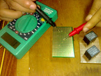
1st Step : Checking connection on the copper board. For this step, We must know Which line on the copper boards are touch to each other. We check the connection by using the multimeter - set the selector at the buzzer. The buzzer will produce sound if there is any touch point on the board.
2nd Step : Soldering Relays - There are four relays that we have to solder. Firstly, we solder the pin for common and NO. Then we solder the pin for switch and ground. We solder the jumper to each pin in order to construct the circuit based on the circuit diagram.
3rd Step : After finish soldering the relays, we solder the ground and supply of the circuit in separate copper board. We separate the board because we want to avoid any short circuit. Two long jumper were soldered in order to connect with the Power Supply.
Thursday, March 4, 2010
Construct Circuit on the Breadboard - Part 2
To understand the concept of relay is very important in constructing the circuit. The common and NO pins are connected to the push button located on the remote control circuit. Pin 1 and pin 2 are the connection for switch and ground. We supplied 5 VDC to the circuit. The other pins of the switch is connected to the supply. There are four switches used in this circuit to control and conduct the current to operate the relays.
Wednesday, March 3, 2010
Construct Circuit on the Breadboard
For the first time we construct the circuit, it doesn't work as it should be. The problem is we make wrong connection for the relays. Then we do the continuity test in order to check the connection of the relays. Firstly we have to determine the common pin. Then we have to determine the NC pin and NO pin. We test the circuit by connecting the probe to the common and NO pins. Once we push the control button, the buzzer of the multimeter will 'buzz' if common pin connected with the NO pin.
Monday, March 1, 2010
Modifying the circuit
After the investigation, we need to modify the circuit before we can program it. In this case, we need to connect the relays to each of the four buttons on the circuit. We have bought the components and prepared the tools used to construct the circuit. The components are the four 6 Volts relays. The pictures show the components and tools that we prepared for constructing the circuit.
Saturday, February 27, 2010
Designing the Circuit Diagram
The picture above is the circuit diagram that we want to modify for the remote control. Four 6 volts relays used to connect with the push buttons at the remote control circuit. Relays function as a switch to operate the remote. For this circuit, we use 5 pins relay. Relays have two circuits which are a control circuit and a load circuit. The relay's switch connections are usually labelled COM, NC and NO:
COM = Common, It is the moving part of the switch.
NC = Normally Closed, COM is connected to NC when the relay coil is off.
NO = Normally Open, COM is connected to NO when the relay coil is on.
Wednesday, February 24, 2010
Investigate the circuit in the remote control
We have discussed with our supervisor about the circuit. Based on the discussion, we just have to modify the circuit in the remote control. Firstly we have to identify on how many buttons that we need to program. We have checked out the circuit and found that there are four push buttons used by the thumb-stick which are the up, down, left and right.
Tuesday, February 2, 2010
View the circuit
This Stunt vehicle has a very complicated circuit and it is very compact.
The circuit consist of transmitter and receiver. We still couldn't explore the circuit since it is very compact and small. Otherwise we don't have the schematic diagram.
The transmitter fitted at the remote control in order to transmit the signal to the receiver circuit that fitted inside the car. The circuit has its brain which is the micro-controller that program and process the movement of the car. The front and the rear motor act as the output of this product that perform the movement.
Sunday, January 31, 2010
Start Experimenting
Once we get the RC Stunt Car, we have started experimenting the vehicle. We tried play the vehicle. During the experiment, we tried to perform the move that the vehicle should perform. It is quiet difficult at first we control the vehicle but the more we explore the controller, than we success to perform some special moves that is interesting to watch.
Friday, January 29, 2010
Build an RC Dancing Vehicle
Our final project is "Radio Controlled Vehicle with Programmable Move" or we call it "Wireless Dancing Car". We are going to modify the existing RC Stunt Car by programming the vehicle with certain moves that is easier to control. The existing product is using the remote control that requires the skill of the users to perform the move such as twist, circle 360 degrees and super stepped. So our objective for this project is to program the special move by pushing the buttons.
Subscribe to:
Posts (Atom)